logo
Отправить сообщение
Shenzhen Olax Technology CO.,Ltd
О нас
Ваш профессиональный и надежный партнер.
Shenzhen OLAX Technology Co., Ltd., которая расположена в Шэньчжэне, Китай.Он является ведущим отечественным поставщиком технологических решений и оборудования для беспроводных коммуникаций..Наши основные продукты 4G C P E WIFI маршрутизаторы, USB WIFI dongles, модемы. карманный WIFI hotspot.G S M и C D M A фиксированные беспроводные телефоны, терминалы, Кроме того, мы поддерживаем блокировку карт,Сетевая блокировка и безопасность SIM-карты.У нас есть основная команда с более чем десятилетним о...
Узнайте больше

0

Год создания:

0

Миллион+
Работники

0

Миллион+
Служение клиентам

0

Миллион+
Годовой объем сбыта:
КИТАЙ Shenzhen Olax Technology CO.,Ltd Высокое качество
Печать доверия, проверка кредитоспособности, RoSH и оценка способности поставщика. Компания имеет строгую систему контроля качества и профессиональную лабораторию.
КИТАЙ Shenzhen Olax Technology CO.,Ltd Развитие
Внутренняя профессиональная команда дизайнеров и мастерская передовых машин. Мы можем сотрудничать, чтобы разработать продукты, которые вам нужны.
КИТАЙ Shenzhen Olax Technology CO.,Ltd Производство
Продвинутые автоматические машины, строгая система управления процессом. Мы можем изготовить все электрические терминалы за пределами вашего спроса.
КИТАЙ Shenzhen Olax Technology CO.,Ltd 100% СЕРВИС
Насыщенная и индивидуальная небольшая упаковка, FOB, CIF, DDU и DDP. Позвольте нам помочь вам найти лучшее решение для всех ваших проблем.

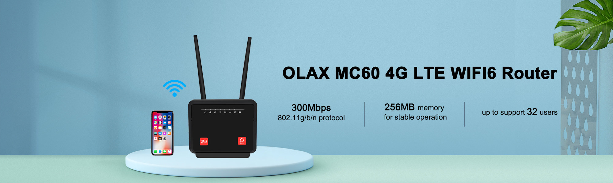
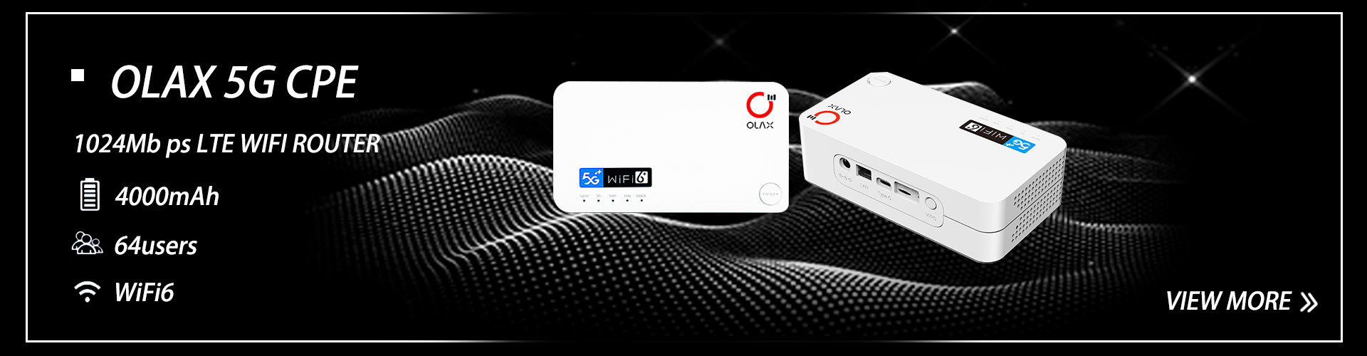
качество Портативные маршрутизаторы Wifi & Беспроводные маршрутизаторы WIFI производитель

Найдите продукты, которые лучше отвечают вашим требованиям.
Случаи и новости
Последние горячие точки
USIM в системе 5G (NR) (1)
1.UE и UICC В системе мобильной связи, определенной 3GPP (Проект партнерства третьего поколения), терминальное устройство пользователя (UE) состоит из:ME (мобильное оборудование) + UICC (Универсальная карта интегральной схемы); где UICC представляет собой физические карты, которые защищены от подделки и устойчивы к программным и аппаратным атакам. 2. UICC и USIM UICC могут содержать несколько приложений, одним из которых является USIM; USIM безопасно хранит и обрабатывает все конфиденциальные данные, связанные с пользователем и домашней сетью.USIM контролируется оператором домашней сети; оператор выбирает данные, которые необходимо настроить в USIM до их выдачи, и удаленно управляет USIM на устройстве пользователя с помощью механизма OTA (over-the-air). 3.USIM в 5G 3GPP определяет USIM для системы 5G в Rel-15 для доступа и использования в сетях 3GPP и не 3GPP, позволяющих UE (пользовательское оборудование) внешние сети передачи данных.USIM определяется в Rel-16 как аутентификация сетевого сегмента. 4.Первая аутентификация является обязательной процедурой, позволяющей UE (пользовательскому оборудованию) получить доступ к сетям 3GPP или не 3GPP. EAP-AKA' or 5G-AKA are the only authentication methods that allow primary authentication and the subscription credentials are always stored in the USIM when the terminal supports 3GPP access functionalityДля первичной аутентификации на основе AKA,взаимная аутентификация, выполняемая в USIM, и генерация ключевого материала (ключ целостности IK и ключ конфиденциальности CK), отправленный USIM в ME, остаются неизменными по сравнению с 3G, 4G и соответствует спецификации 3GPP TS 33.102 [3].Изменения в 5G Primary Authentication USIM включают хранение нового контекста безопасности и дополнительного ключевого материала в USIM (в зависимости от конфигурации USIM). 4.1 Поддержка 5G Если USIM поддерживает хранение параметров 5G, ME будет хранить новый контекст безопасности 5G и новые ключи, определенные для иерархии ключей 5G (т.е. KAUSF, KSEAF и KAMF) в USIM.USIM может хранить контекст безопасности 5G для сетей доступа 3GPP и контекст безопасности 5G для сетей доступа, не являющихся 3GPPХранение контекста безопасности и ключевого материала в USIM обеспечивает более быстрое воссоединение при роуминге (UICC перемещается из одного ME в другой). 4.2 Поддержка NPN Аутентификация в частных сетях (так называемых независимых непубличных сетях) может основываться на системе EAP, поддерживаемой системой 5G;пользовательское оборудование и сервисные сети могут поддерживать 5G AKA, EAP-AKA" или любого другого метода аутентификации EAP ключевого поколения, где: ·При использовании методов аутентификации на основе AKA применяется пункт 6.1 3PPTS 33501[1]. ·При выборе другого метода аутентификации EAP, кроме EAP-AKA', выбранный метод определяет необходимые учетные данные в UE и сети.Как эти учетные данные для других методов ОВП, кроме EAPAKA', хранятся и обрабатываются в ЕС, не подпадает под действиеНо для обеспечения высокого уровня безопасности доступа к частным сетям, private network operators may decide to require the presence and use of a UICC containing USIM applications in order to securely store and process subscription credentials for EAP methods such as EAP-AKA' or EAP-TLS . 5. Вторичная аутентификация Это необязательная аутентификация, основанная на EAP, проводимая между UE (устройством пользователя) и DN (внешняя сеть данных).Хотя выбор метода аутентификации и учетных данных EAP выходит за рамки 3GPP, внешние сети обработки данных могут решить защитить доступ к своему DN посредством сильной аутентификации с помощью метода аутентификации EAP-AKA" или EAP-TLS,UICC в устройстве пользователя Наличие USIM на DN безопасно хранит и обрабатывает учетные данные, используемые для доступа к DN. Сетевая аутентификация с использованием сетевой аутентификации с использованием устройства пользователя и AAA (Authentication,Авторизация и учет) сервер для доступа к сетевой части является необязательным. Специфическая аутентификация сетевого фрагмента основана на структуре EAP, и ее идентификатор пользователя и учетные данные отличаются от учетных данных подписки 3GPP.Он следует обязательной первичной сертификацииЗаинтересованные стороны, развертывающие слайсы, могут решить установить USIM на UICC устройств пользователей, чтобы обеспечить высокий уровень безопасности для доступа к своим слайсам и предотвратить появление несанкционированных пользователей.
Инновации в технологии SIM: подробный взгляд на eSIM и vSIM
01.eSIM   eSIM,известный какВстроенная SIM-карта, илиВстроенная SIM-карта, является программируемой электронной технологией SIM-карты, основная особенность которой заключается в том, что она не требует физического слота,но скорее встроенный чип, который интегрирован непосредственно в плату устройства или внутри других устройств. Часть оборудования     Чип интегральной схемы (IC):В центре eSIM находится небольшой IC-чип, который встроен в материнскую плату устройства, похожий на физическую SIM-карту.EEPROM и серийный блок связи) для хранения и обработки данных SIM.   Часть программного обеспечения     Операционная система (ОС):На чипе eSIM работает выделенная операционная система, часто называемая eUICC (Embedded Universal Integrated Circuit Card), которая управляет функциями SIM, включая хранение данных,безопасная обработка и связь.     Процесс производства eSIM   1 Производство микросхем 2 Испытания чипов 3 Интеграция в устройства 4 Загрузка встроенного программного обеспечения 5 Функциональные испытания и проверка   Виртуальная SIM (vSIM)является технологией SIM-карты без физического форм-фактора, которая позволяет устройствам реализовывать функции связи через программное обеспечение, включая SoftSIM, CloudSIM и другие.   02.Виртуальная SIM (vSIM)   Виртуальная SIM (vSIM)является технологией SIM-карты без физического форм-фактора, которая позволяет устройствам реализовывать функции связи через программное обеспечение, включая SoftSIM, CloudSIM и другие.   SoftSIMконтролирует информацию, записанную в SoftSIM через поставщика терминала,и пользователь покупает и использует услуги связи непосредственно через программное обеспечение без вмешательства оператора, что отключает прямую связь между пользователем и оператором.   CloudSIMявляется своего рода функцией SIM-карты, реализованной на основе технологии облачных вычислений, где пользователи используют сетевые услуги на своих устройствах через облачные услуги.   03.Процесс активации службы SIM   CloudSIMинтегрирует трафиковые ресурсы каждого оператора в облако, выбирает операторов в зависимости от качества сигнала и сети в разных регионах,и подталкивает их к терминалам, чтобы предоставить пользователям лучшие сетевые услугиВключение нескольких операторов облегчает пользователям гибкий выбор более выгодных пакетов.       Хотите узнать больше о SIM-картах и других коммуникационных темах? Мы будем продолжать делиться больше об этом! Увидимся в следующем выпуске!
CM (Connection Management) Status of 5G Terminals
  Two CM (Connection Management) statuses are used in the 5G (UE) system to reflect the NAS signaling connection between the terminal (UE) and the AMF. They are: CM-IDLE CM-CONNECTED   I. 5G Terminal (UE) Connection Status When the terminal accesses 3GPP and non-3GPP systems, its CM status is independent of each other. That is, one CM status can be in CM-IDLE state, while the other CM status can be in CM-CONNECTED state.   II. CM-IDLE State When in CM-IDLE:   2.1 The 5G terminal (UE) has not established a NAS signaling connection with the AMF through N1; at this time, the UE performs cell selection/cell reselection according to TS 38.304[50] and PLMN selection according to TS 23.122[17]. The UE has no AN signaling connection, N2 connection, or N3 connection. If the UE is simultaneously in CM-IDLE and RM-REGISTERED states (unless otherwise specified in Clause 5.3.4.1), the UE shall: Respond to paging by executing the service request procedure (see Clause 4.2.3.2 of TS 23.502 [3]), unless the UE is in MICO mode (see Clause 5.4.1.3); Execute the service request procedure when the UE has uplink signaling or user data to send (see Clause 4.2.3.2 of TS 23.502 [3]). LADN has specific conditions (see Clause 5.6.5).   2.2 When the UE state in the AMF is RM-REGISTERED, the terminal information required to initiate communication with the UE shall be stored. The AMF shall be able to retrieve the stored information required to initiate communication with the UE using 5G-GUTI. ---- In 5GS, paging is not required using the UE's SUPI/SUCI.   2.3 During AN signaling connection establishment, the UE shall provide 5G-S-TMSI as part of the AN parameters in accordance with TS 38.331[28] and TS 36.331[51]. When the UE establishes an AN signaling connection with the AN (entering the RRC_CONNECTED state via 3GPP access, establishing a UE-N3IWF connection via untrusted non-3GPP access, or establishing a UE-TNGF connection via trusted non-3GPP access), the UE shall enter the CM-CONNECTED state. Sending an initial NA message (registration request, service request, or deregistration request) initiates the transition from CM-IDLE to CM-CONNECTED state.   2.4 When the AMF is in the CM-IDLE or RM-REGISTERED state, the AMF should execute a network-triggered service request procedure when it needs to send signaling or mobile terminal data to the UE. This is done by sending a paging request to the UE (see Section 4.2.3.3 of TS 23.502[3]), provided that the UE is not unable to respond due to MICO mode or mobility restrictions. Among them:   When the AN and AMF establish an N2 connection for the UE, the AMF should enter the CM-CONNECTED state. Receiving an initial N2 message (e.g., N2 INITIAL UE MESSAGE) will trigger the AMF to transition from the CM-IDLE state to the CM-CONNECTED state. When the UE is in the CM-IDLE state, the UE and AMF can optimize the UE's power efficiency and signaling efficiency, for example, by activating MICO mode (see Section 5.4.1.3).   III. CM-CONNECTED State The UE in the CM-CONNECTED state establishes a NAS signaling connection with the AMF through N1. NAS signaling connections utilize the RRC connection between the UE and the NG-RAN, and the NGAP UE association between the AN and the AMF, to achieve 3GPP access. The UE can be in the CM-CONNECTED state, but its NGAP UE association is not bound to any TNLA between the AN and the AMF.   For a UE in the CM-CONNECTED state, the AMF can decide to release the NAS signaling connection with the UE after the NAS signaling procedure is completed.   3.1 In the CM-CONNECTED state, the UE should: Enter the CM-IDLE state when the AN signaling connection is released (e.g., entering the RRC_IDLE state via 3GPP access, or when the UE detects the release of the UE-N3IWF connection via an untrusted non-3GPP access, or the release of the UE-TNGF connection via a trusted non-3GPP access).   3.2 When the UE's CM state in the AMF is CM-CONNECTED, the AMF shall:   --When the UE's logical NGAP signaling connection and N3 user plane connection are released after the AN release procedure specified in TS 23.502[3] is completed, the UE shall enter the CM-IDLE state.   --The AMF may maintain the UE's CM state in the CM-CONNECTED state until the UE is deregistered from the core network.   3.3 A UE in the CM-CONNECTED state may be in the RRC_INACTIVE state, see TS 38.300[27]. When the UE is in the RRC_INACTIVE state, the following rules apply: - UE reachability is managed by the RAN and auxiliary information is provided by the core network; - UE paging is managed by the RAN; - The UE listens for paging using its CN (5G S-TMSI) and RAN identifier.

2025

12/09

Key Technical Points of 5G Radio Group RAN1 in R18
  3GPP Release 18 is the first 5G-Advanced release, focusing on AI/ML integration, ultimate performance in XR/Industrial IoT, mobile IAB, enhanced positioning, and spectrum efficiency up to 71GHz. RAN1 further promotes AI/ML enhancements in RAN optimization and artificial intelligence (PHY/AI) through physical layer evolution.   I. Key Features of RAN1 (Physical Layer and AI/Machine Learning Innovations)   1.1 MIMO Evolution: Multi-panel uplink (Level 8), MU-MIMO with up to 24 DMRS ports, multi-TRP TCI framework.   Operating Principle: Extends Type I/II CSI reporting through a unified TCI framework across multiple TRP panels. The gNB schedules up to 24 DMRS ports for MU-MIMO (12 in Rel-17), enabling each UE to use Level 8 UL links; DCI indicates joint TCI status; UE applies phase/precoding across panels. Progress: The lack of unified signaling in Rel-17 multi-TRP resulted in a 20-30% loss of spectral efficiency in dense deployments; level restrictions limited the UL throughput of each UE to layers 4-6, thereby achieving a 40% increase in uplink (UL) capacity for stadiums/music festivals.   1.2 AI/ML Applications to CSI Feedback Compression, Beam Management, and Positioning.   Working Principle: The neural network uses an offline-trained codebook to compress Type II CSI (32 ports → 8 coefficients). The gNB deploys the model via RRC; the UE reports the compressed feedback. Beam prediction uses the L1-RSRP mode to pre-position beams before handover. Project Progress: CSI overhead consumed 15-20% of DL resources; in high-mobility scenarios (e.g., highways), beam management failure rates reached as high as 25%. Improvement Results: Channel State Information (CSI) overhead reduced by 50%, handover success rate improved by 30%. 1.3 Enhanced Coverage (Uplink full-power transmission, low-power wake-up signal).   Operating Principle: The gNB sends a signal to the UE, enabling it to apply full power output across all uplink layers (without tiered power backoff). An independent low-power wake-up receiver (duty cycle controlled, sensitivity -110dBm) receives the wake-up signal (WUS) before the main receive cycle. The WUS carries 1 bit of indication information (monitoring PDCCH or sleep). Project Progress: Rel-17 uplink coverage is limited by tiered power backoff (4th order MIMO loss of 3dB); the main receiver consumes 50% of the UE's power during DRX monitoring. Improvements: Uplink coverage extended by 3dB; IoT/video streaming applications saved 40% of power. 1.4 ITS Band Sidelink Carrier Aggregation (CA) and Dynamic Spectrum Sharing (DSS) with LTE CRS.   Operating Principle: Sidelink supports CA across the n47 (5.9GHz ITS) + FR1 bands; supports autonomous resource selection for Type 2c coordination among UEs. Due to a round-trip time (RTT) greater than 500 milliseconds, NTN IoT disables HARQ (only supports open-loop repetition); pre-compensation is implemented for the Doppler effect in DMRS. Project Progress: Rel-17 Sidelink only supports single-carrier (50% throughput loss); NTN IoT HARQ timeouts result in 30% packet loss. Improvements: V2X formation sidelink throughput is increased by 2x, and NTN IoT reliability reaches 95%. 1.5 Extended Reality (XR)/Multi-sensor Communication (High Reliability, Low Latency Support).   Operating Principle: New QoS procedure, latency budget less than 1 millisecond, supports multi-sensor packet tagging (video + haptic + audio stream). gNB prioritizes data through a preemption mechanism. UE reports attitude/motion data for predictive scheduling. Project Progress: Rel-17 XR support only supports unicast; haptic feedback latency exceeds 20 milliseconds (unusable for remote operation). Improvements: End-to-end latency of AR/VR + haptic in industrial remote control is less than 5 milliseconds.   1.6 NTN Functionality Enhancement (Smartphone Uplink Coverage, Disabling HARQ for IoT Devices).   How it Works: Rel-18 improves the uplink coverage of smartphones in non-terrestrial networks (NTNs) by optimizing physical layer transmission, allowing for higher transmit power and better link budget management to accommodate satellite channels. For IoT devices on NTNs, traditional HARQ feedback is inefficient due to long satellite round-trip times (RTTs), therefore HARQ feedback is disabled, and an open-loop repetition scheme is adopted instead. Project Progress: Previously, due to insufficient power control and link margin, the uplink coverage of smartphones on NTNs was limited, resulting in poor connectivity. HARQ feedback caused throughput reduction and latency issues for IoT devices due to satellite latency. Disabling HARQ eliminates feedback latency and improves the reliability of constrained IoT devices. This enables robust global connectivity for IoT and smartphones beyond terrestrial networks. II. RAN1 Project Applications Dense Urban XR (Multi-TRP MIMO technology reduces AR/VR latency to below 1 millisecond); Industrial Automation (AI/ML beam prediction reduces handover failure rate by 30%); V2X/High Mobility (Sidelink CA improves reliability).   III. RAN1 Project Implementation gNB PHY (Base Station Physical Layer): Integrates an AI model for CSI compression (e.g., neural networks predict Type II CSI based on Type I CSI, reducing overhead by 50%). Deploys Multi-TRP TCI via RRC/DCI and uses 2 TAs for uplink timing. Terminal Equipment (UE): Supports low-power wake-up receivers (independent of the main RF link) for DRX alignment signaling.

2025

12/08

5G Radio Working Group (RAN3) R17 Key Work Highlights
  RAN3 Release 17 focuses on major evolutions in 5G (NR), bringing enhancements to key architectures such as native multi-access edge computing (MEC) support, the introduction of reduced-capacity RedCap for IoT, enhanced sidechains, positioning and MIMO, and increased support for new frequency bands (up to 71 GHz) and non-terrestrial NTN. All of these improvements are built upon core network function evolution to enhance spectrum efficiency and device power saving, enabling broader 5G applications.   I. Key Features of RAN3 in Release-17 IAB Function Enhancements—Improved resource reuse, topology robustness, and routing options between IAB parent and child links. NTN (Non-Terrestrial Network) Architecture—System architecture supports integration of satellite/HAP with terrestrial 5G (NR). NPN (Non-Public Network) Enhancements and Edge Computing Integration Support. II. Key Technical Details and System Integration of RAN3   2.1 Enhanced IAB (Integrated Access and Backhaul) Technology Resource Reuse: Rel-17 defines additional mechanisms that enable IAB nodes to allocate resources more flexibly between access (to UE) and backhaul (to child IAB nodes) based on existing scheduling. Specifically: Updating F1/Xn internal signaling between the parent node and the IAB-DU/MT. Achieving robust path management and rerouting—the IAB control plane (IAB-CU) must be able to reallocate provider relationships in the event of link failure. Topology and Routing: Support for semi-static routing table updates and enhanced bearer mapping; vendors need to test congestion/priority rules for backhaul and access traffic. 2.2 NTN Architecture   GW and NG-RAN Integration: Rel-17 defines NTN Stage 2/Stage 3 architectural changes to support satellite link features end-to-end. Implementers must coordinate with the CN (SA/CT) to support PDU sessions and mobility differences (such as longer handover times due to GEO/LEO satellite movement).   Timing and Synchronization: NTN nodes typically require GNSS/time distribution (or alternative time synchronization) and specific handling of timing advance and HARQ timers within the RAN architecture is necessary.

2025

12/06